Rev 2 PCB Design and Errata
New Features on Rev 2 PCB
USB Charger circuit
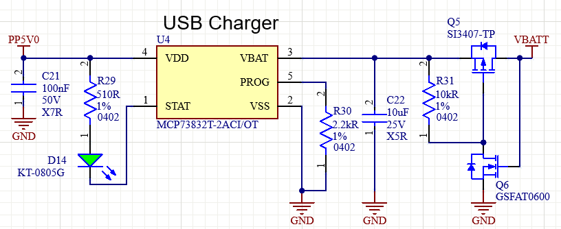
USB Charger Circuit
Using the 5V USB input pin on ESP dev board, the circuit charges the lipo battery with 500mA maximum charge current.
- Q6 detects whether the battery is connected or not. When battery is disconnected, Q5 disconnects the charger from battery rail.
- STAT LED lights up while the battery charging is in progress.
System Power Switch
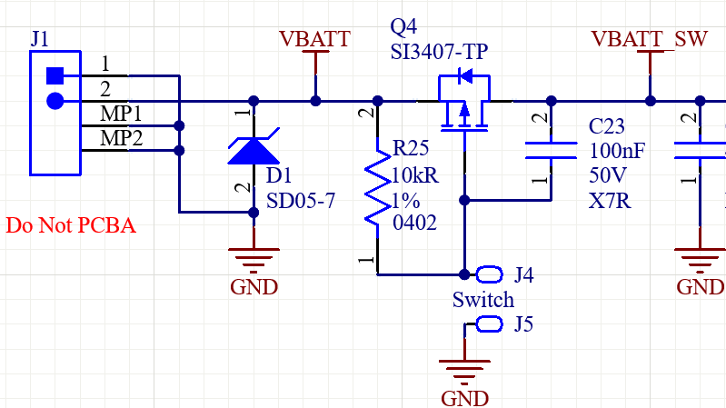
Power Switch Circuit
Q4 connected with slide switch (soldered with wires on J4 and J5) can disconnect the system from the battery when the system’s not in use.
Reworks done on Rev 2 PCB
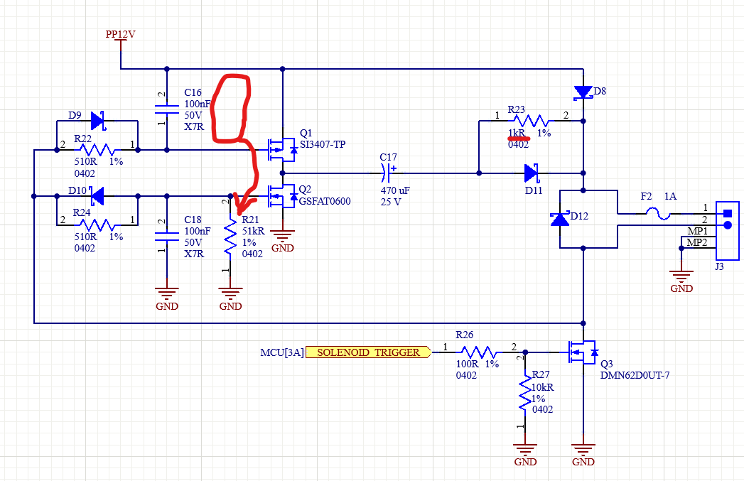
- R21 Pull-up resistor is moved to pull-down, as pull-down at Q2 gate provides better protection against shoot through in open-load, power-up situation compared to pull-up on Q1.
- R23 resistance is changed to 1kR from 10kR to increase charging speed of C17. 1kR is high enough to prevent significant amount of current from being pulled during actuation.
- C17 capacitor value is increased to 820 uF to provide stronger initial push.
Rev 2 PCB Reworks