AB Testing
Criteria
Each item below is tested on the foot model with and without the protection engaged.
- Time stayed above 400 deg/s inversion speed
- Stopping position of ankle
Procedure
- Pull the string attached to the foot brace with a gentle jerk motion with the protection engaged.
- Record the IMU’s inversion speed reading as well as the video of inversion sequence.
- Take a photo of the ankle’s final position.
- Repeat without the protection.
Note: due to limitation in 3D printed mechanism causing slipping in gear and latch, inversion motion is tested with manual pulling of string instead of dropping weight at fixed height. The test is to be repeated when machined parts are assembled.
Results
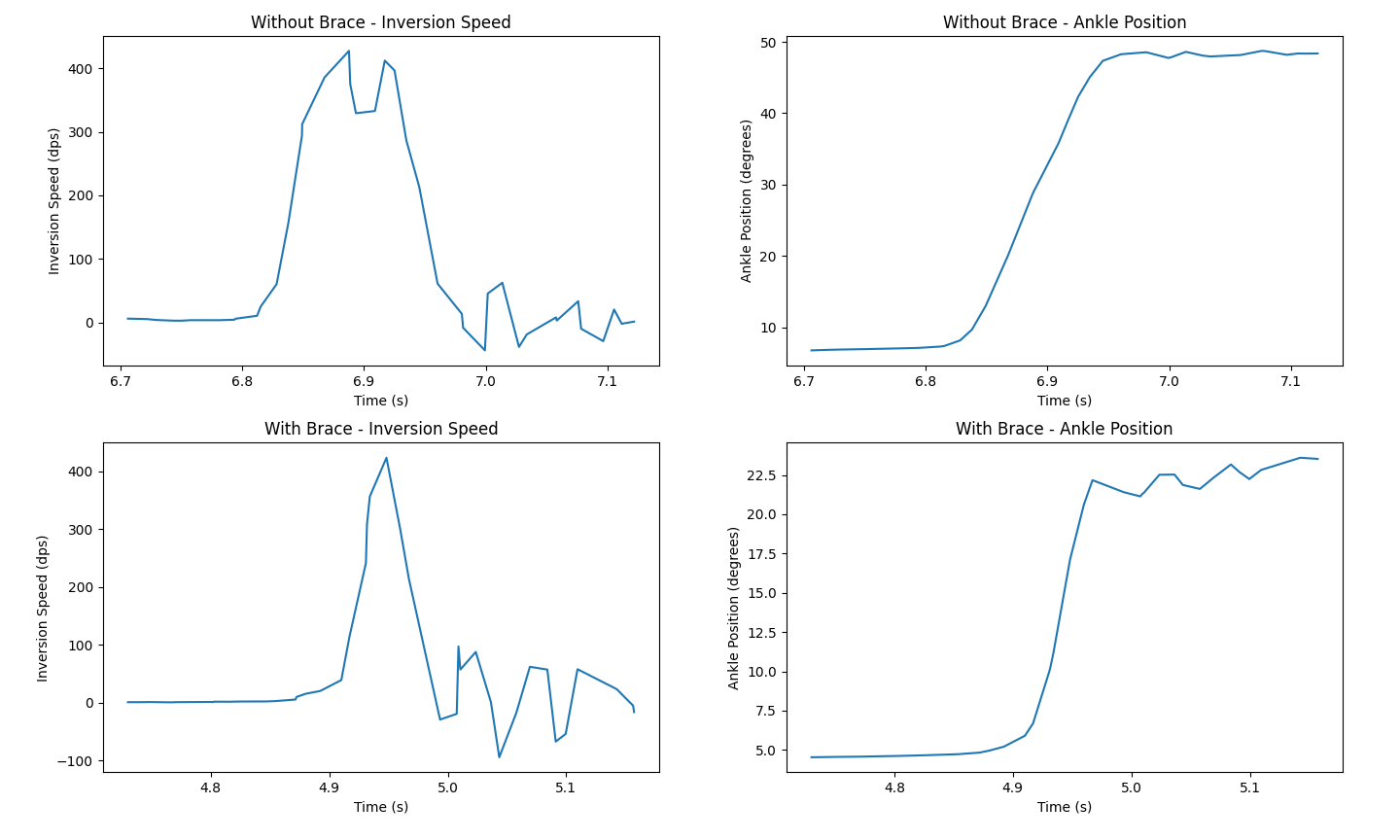
AB Test Results
Looking at the inversion speed plots on the left side of the figure above, a clear difference in the width of the inversion speed pulse can be seen. The inversion speed without protection engaged stays above 400 deg/s for more than ~40 ms. This results in the foot model hitting the maximum range of motion of about 48 degrees in less than 100 ms.
In contrast, inversion speed with brace stays above 400 deg/s for a single IMU sample only, and sharply dropping afterwards. The effectiveness of brace can be seen in the inversion angle plot on the bottom right side of the figure as well. The protection mechanism engages in less than 50 ms of ankle inversion starting and stops the ankle at about 22.5 degrees.
Below pictures and videos are from the AB testing above.
With protection engaged:
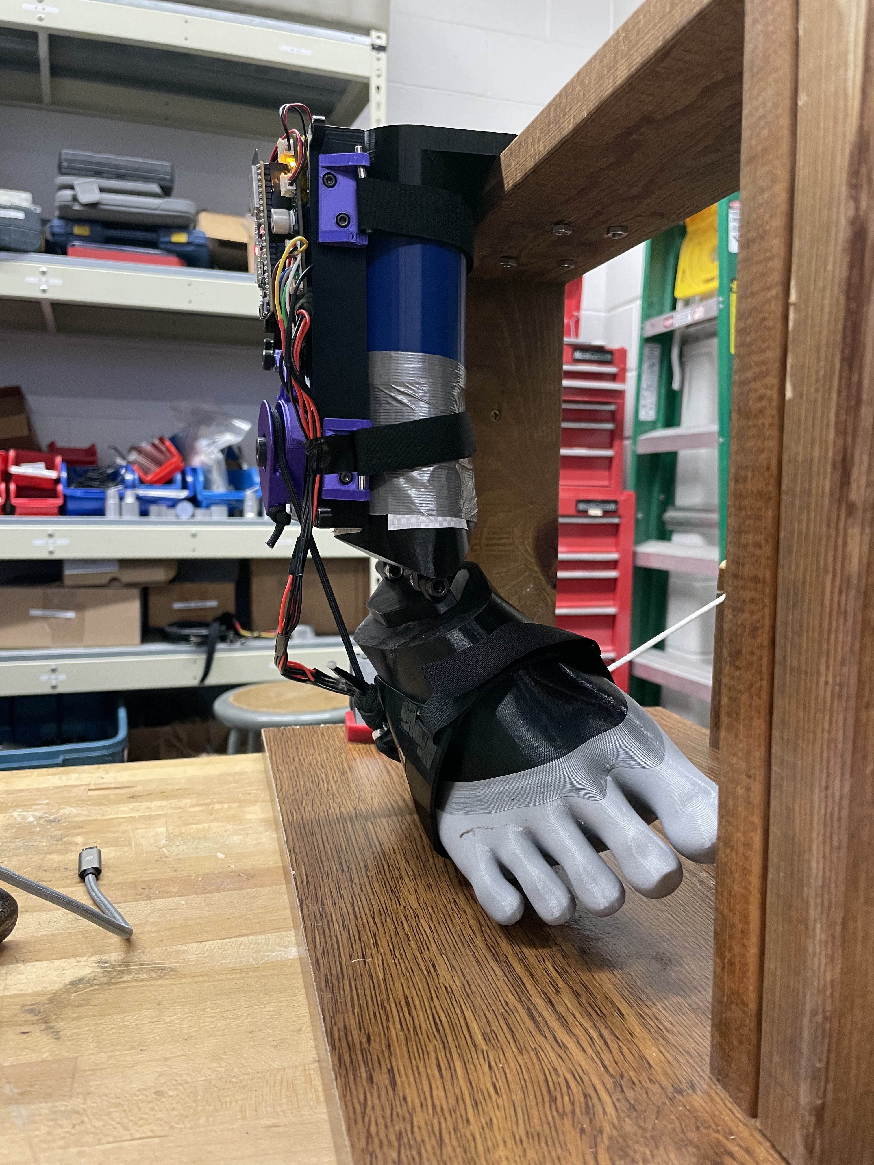
Ankle Inverted Position With Brace Protection
Test With Brace Protection
Without protection engaged:
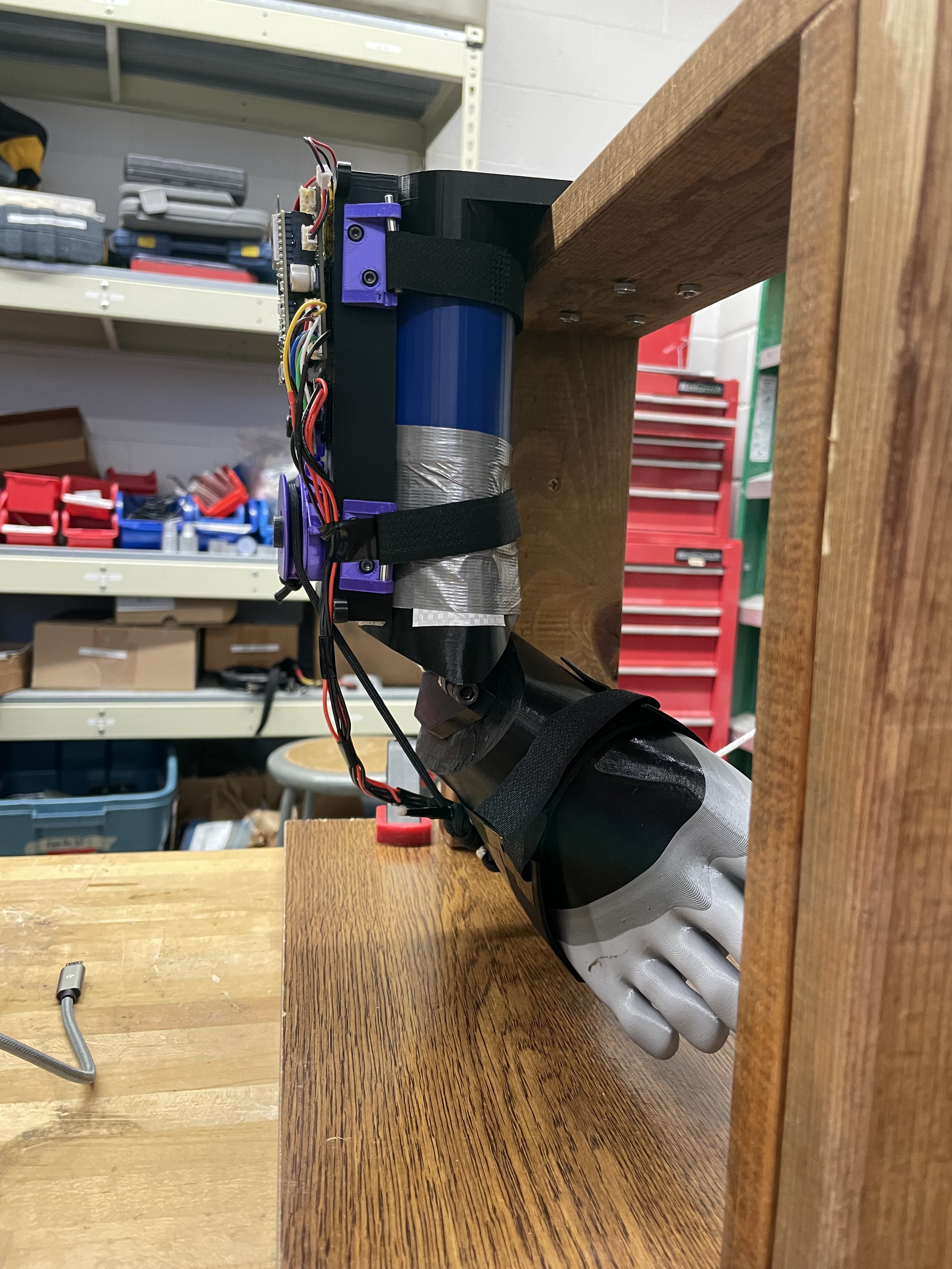
Ankle Inverted Position Without Brace Protection
Test Without Brace Protection