Rev 1 PCB Bring-Up
This post describes the testing performed to validate the Revision 1 custom PCB.
Test 1: Battery Startup Check
Goal: Verify that the capacitive inrush does not trip the battery protection circuit and powers up the board successfully
Result: Pass
Test 2: 3V3 Power Supply Characterization
Goal: Verify the power supply can support stable 3.3V rail for MCU
Results: Pass
- Load Transient from 0 → 500mA: less than 50mV drop on Vout
- Steady state peak to peak V ripple: 50mV at 0mA, 8mV at 500mA
Test 3: Solenoid driving without boosting driver circuit
Goal: Checking solenoid driver circuit’s functionality without voltage boost circuit
Results: Fail → Pass
- Initial attempt failed:
- 12V rail dropping to 8.6V observed → Overcurrent protection trip suspected
- Modified R_ILIM value from 1MR to 330kR to increase current limit
- Solenoid driving passed after increasing overcurrent protection limit
Test 4: Solenoid driver half bridge gate network functionality check
Goal: Without the half bridge assembled, check the gate voltage waveform to verify PMOS and NMOS won’t turn on at the same time and cause short
Result: Fail → Pass
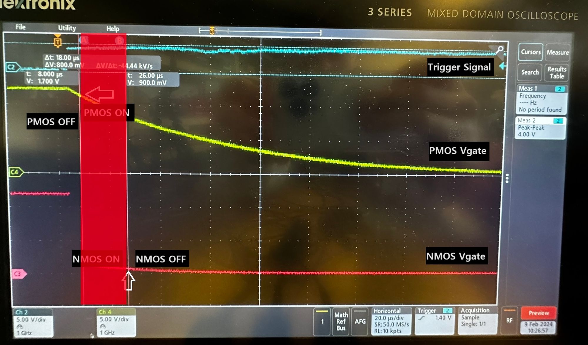
MOSFET Gate Voltages
Initial investigation revealed that with the current selection of transistors, which has Vth ~ 1V, trigger signal will create a 18 us window where both transistors are turned on, creating short from 12V to GND.
To address this issue, transistors in half bridge are replaced with higher threshold voltage transistors (Vth ~ 3V), which gives about 14 us of deadtime when switching happens.
Test 5: Fully assembled solenoid driver test
Step 1: Half bridge functionality check with transistor assembled
Issue encountered: Low side NFET destroyed when trigger signal low and solenoid disconnected.
- Pull-up resistor on PFET gate and pull-down resistor on NFET forms voltage divider when solenoid is disconnected, turning on both FETs and frying NFET with lower current limit.
- Removing the pull-down resistor on NFET resolved the issue.
Step 2: Check voltage across solenoid with fully assembled driver including boost capacitor
Result: Pass
As observed below, 24V peak voltage is applied across the solenoid, duplicating the behaviour observed in LTSpice simulation.
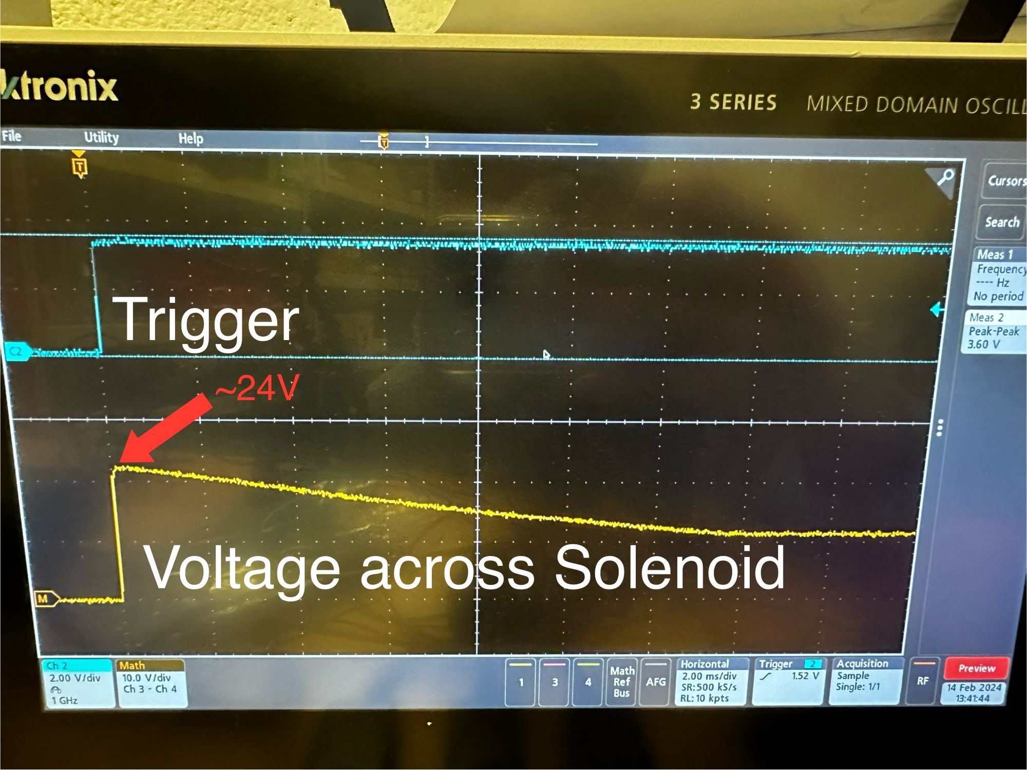
Voltage Across Solenoid