IMU Inversion Measuring
IMU Coordinate System
To measure ankle inversion speed with the double IMU setup, we need to figure out a way of referencing IMU measurements in the same frame of reference. The IMUs are mounted on the foot with approximately the following configuration:
- IMU A with reference frame {a} mounted on the lower leg
- IMU B with reference frame {b} mounted on the foot
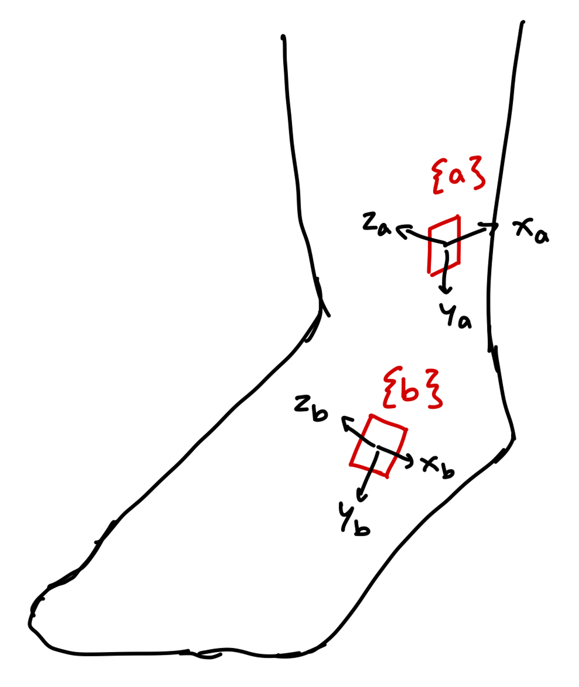
IMU Sensor Frames
We need to obtain the rotation matrix \(R_b^a\) which maps from sensor frame {b} to sensor frame {a}. To do this, obtain the normalized acceleration vectors measured by the IMUs at resting position (call them \(\hat g_a\) and \(\hat g_b\)). These are the measured unit gravity vectors in frames {a} and {b} respectively. Then:
- Let \(v=\hat g_b\times \hat g_a\)
- Let \(c=\hat g_b\cdot \hat g_a\)
Then the rotation matrix can be computed as:
\[R_b^a=I+[v]_x+[v]_x^2 \frac{1}{1+c}\]where
\[[v]_x:=\begin{bmatrix}0&-v_3&v_2\\v_3&0&-v_1\\-v_2&v_1&0\end{bmatrix}\]is the skew-symmetric cross-product matrix of \(v\) (source).
With the above mounting scheme, if we assume that the positive inversion direction is rotation about the \(x_a\) axis (referenced in sensor frame {a}), then we can measure inversion velocity as:
\[\omega_{inversion}=(R_b^a\omega_b-\omega_a)_1\]where \(\omega_a\) and \(\omega_b\) are gyroscope measurements from IMUs A and B, respectively. Note that \((x)_1\) here means the first element of vector \(x\).
Testing
The following video shows the test setup of the IMU inversion measuring scheme. The live plotter shows the measured inversion velocity in degrees per second of the model test foot.