Solenoid Characterization
We procured a 12V, 4mm stroke solenoid for use in our actuation mechanism.
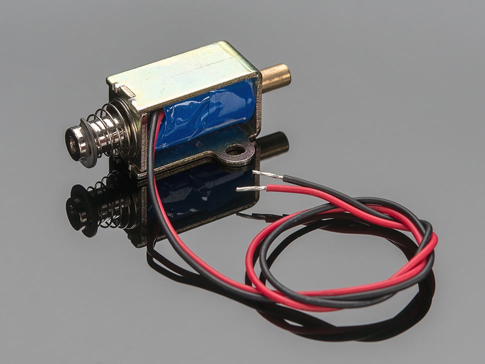
Small Push-Pull Solenoid - 12VDC
Below is the characterization work done to verify if this solenoid can actually meet our 40ms system response time requirement.
Reaction Speed
Setup:
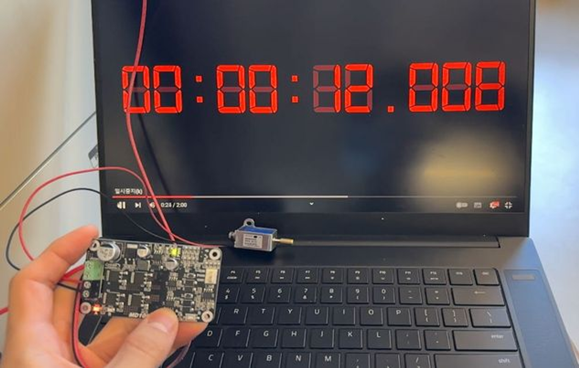
Time is measured with 120 fps stopwatch from youtube, displayed on 144 fps monitor.
Reaction time is defined as the time from the light up of the LED on motor driver to the time the solenoid fully actuates. The tables below summarize the results of reaction time measurements.
12V
| Solenoid 1 | LED on time | Solenoid on time | Delay |
|---|---|---|---|
| Trigger 1 | 9.542 | 9.675 | 0.133 |
| Trigger 2 | 11.568 | 11.625 | 0.057 |
| Trigger 3 | 13.517 | 13.592 | 0.075 |
| Solenoid 2 | LED on time | Solenoid on time | Delay |
|---|---|---|---|
| Trigger 1 | 4.475 | 4.575 | 0.1 |
| Trigger 2 | 6.6 | 6.633 | 0.033 |
| Trigger 3 | 8.692 | 8.733 | 0.041 |
Note 1: both solenoids take more than 2x longer to actuate on the first trigger. This behavior seems to be resulting from the magnetization of the ferromagnetic pole, adding extra time on the initial trigger.
Note 2: given that our desired reaction time of the solenoid is within 40ms, neither of the 2 solenoids met our response time expectation.
18V
| LED on time | Solenoid on time | Delay | |
|---|---|---|---|
| Trigger 1 | 5.7915 | 5.808 | 0.0165 |
| Trigger 2 | 7.15 | 7.167 | 0.017 |
| Trigger 3 | 8.442 | 8.467 | 0.025 |
In order to ensure the solenoid actuates fast enough, we tested the effectiveness of pulsing the solenoid at a voltage higher than the rated voltage to ensure that the desired current, which is proportional to force generated, is reached faster.
As shown, increasing the supply voltage by 50% reduced the delay significantly. This result will be taken into account when designing the solenoid driver portion of the PCB.
Inductance and Resistance
A high voltage pulse circuit needs to be designed properly with the right duration and voltage level, so that the current through the solenoid doesn’t exceed a safe level. In order to achieve that, simulating the circuit with the right parameters is important.